
Aktuelle Promotionen
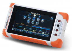
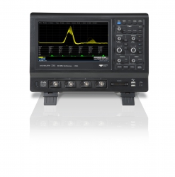
WaveSurfer 3000 Oszilloskop Promotionen
- EMB - Dekodieren und Triggern der Bus-Signale I2C, SPI, UART und RS232
- AUTO - Dekodieren und Triggern der Bus-Signale CAN und LIN
- FG - 1-Kanal Funktions- und Arbiträrgenerator
Testen Sie mich! Fordern Sie eine Gratis-Demo an.
WaveSurfer 3000 Oszilloskop Promotionen
- EMB - Dekodieren und Triggern der Bus-Signale I2C, SPI, UART und RS232
- AUTO - Dekodieren und Triggern der Bus-Signale CAN und LIN
- FG - 1-Kanal Funktions- und Arbiträrgenerator
Testen Sie mich! Fordern Sie eine Gratis-Demo an.
Electromagnetic Compatibility – IEC61000 - 3 - 3:2013 A Technical Guide to Flicker Measurement (E)
Introduction
This technical article will discuss the Electromagnetic Compatibility (EMC) IEC61000 - 3 - 3:201 3 testing standard, including relevant extracts from IEC61000 - 4 - 15(instrumentation oriented standard) and explanations relating to analysis of voltage fluctuations and flicker on public low voltage supply systems. We will also describe how N4L ensure full compliance to the standard, including our Harmonics a nd Flicker Analyzer ( PPA5511 / PPA5531 ), AC Power Source and Impedance Network (Z ref ).
What is Flicker?
The formal definition of flicker is the “impression of unsteadiness of visual sensation induced by a light stimulus whose luminance or spectral distribution fluctuates with time” (IEC 60050 - 161, 1990) Flic ker can be considered as a symptom, resulting from the modulation of a load and its effect on its own terminal voltage. Whilst connected to a voltage source with finite impedance, any load modulation will cause voltage fluctuations on the supply line. IEC6 1000 - 3 - 3:2013 is primarily concerned with the limitation of such fluctuations and subsequent flicker upon public low - voltage systems. IEC61000 - 3 - 3:2013 specifies the limits of voltage changes produced by electrical and electronic equipment when tested unde r these specified conditions.
Windowing
It is common for a power analyzer to use the nominal update rate set by the user ( eg. 500ms) as its internal data acquisition window size , regardless of the motor frequency of the motor drive unit being evaluated . However, o ptimum measurement requires synchronisation of the measurement windo w to the fundamental time period or "motor frequency" (with respect to time) . If the measurement window is correctly sized to a single or even multiple fundamental time periods, RMS calculations of Voltage, Current and Power will be correctly computed . If the acquisition window d oes not contain an exact integer number of cycles, this will cause significant measurement error when update rate s approach the time period of the motor frequency, figure 1 illustrates the issue.
IEC61000 - 3 - 3:2013
IEC61000 - 3 - 2:2013 is applicable to electrical and electronic equipment with an input current rating equal to or less than 16A per phase. Should a device fail the limits specified in IEC61000 - 3 - 3:2013 tested with the specified source impedance specified in section 6.4 (Z ref ), it may be retested to show conformity with IEC61000 - 3 - 11 (discussed in a separate article). Part 3 - 11 is applicable to all equipment with rated input ≤75A per phase and is subject to con ditional connections.
What is Z ref ?
Z ref is the internationally agreed reference source impedance for low - voltage supply networks, as illustrated in the diagram below.
")
Key:
G –Voltage Source
EUT –Equipment Under Tes
tM –Measuring Equipment
S –Supply Source including reference impedance and voltage generator output impedance
RA= 0.24Ω jXA= 0.15Ω @ 50Hz
RN= 0.16Ω jXN= 0.10Ω @ 50Hz
Note: The reference impedance within the source (S) block includes both the output impedance of the AC Source (G) and the reference impedance network (RA,jXA, RN,jXN).
Test Equipment Requirements
In real world compliant flicker testing, Z ref is a physical impedance network consisting of a resistive element and an inductive element that is placed in between the AC Power Source and the equipment under test. N4L can provide the entire test system including Programmable AC Power source, Impedance Network and Flicker (+Harmonics +Power) Analyzer. We will discuss the different elements of the test system below; 1. Programmable AC Power Source - Section 6.3 of IEC61000 - 3 - 3:2013 describes the requirements for the AC Power Source for compliant Flicker Testing; this can be summarized in the table below.

2. Z ref - Reference Source Impedance - Section 6.4 of IEC61000 - 3 - 3:2013 describes the requirements for Z ref IEC61000 - 3 - 3:2013 refers to IEC/TR 60725 which specifies the in - phase and quadrature component of the reference impedance Zref. It is important to note that Z ref includes the impedance of the reference network and the output impedance of the AC source, the output impedance of the N4A series AC Power Sources is very low and can be considered negligible for this application.
3. Flicker Analyzer - Section 4.2.2 of IEC61000 - 3 - 3:2013 refers the reader to IEC61000 - 4 - 15:2010 which lays out the specification and signal process ing requirements for compliant flicker measurements. All N4L PPA551 1 and N4L PPA5531 Harmonics and Flicker Analyzers offer full compli ance to IEC61000 - 4 - 15. Furthermore, N4L are able to offer IEC61000 Harmonics and Flicker calibration to ISO17025 from our in house UKAS Laboratory.
... Please open the pdf-file in order to read the complete article.
... Bitte öffnen Sie die PDF-Datei. um den ganzen Artikel zu lesen.
Conclusion
Flicker analysis is a complex subject, procedures must be in place in order to perform thorough verification of the analyzer. Newtyons4th are an accredited ISO17025 Calibration Laboratory (UKAS) and our scope includes testing of Harmonics and F licker to IEC61000 - 3 - 3 (IEC61000 - 4 - 7), ISO17025 calibration is available directly from Newtons4th.
References:
• International Electrotechnical Vocabulary. (1990). Electromagnetic Compatibility – Chapter 161, IEC 60050 - 161:1990. International Electrotechnica l Vocabulary • International Electrotechnical Commission. (2013). Electromagnetic compatibility (EMC) – Part 3 - 3 Limits – Limitation of voltage changes, voltage fluctuations and flicker in public low - voltage supply systems, for equipment with rated current ≤ 16 A per phase and not subject to conditional connection. International Electrotechnical Commission.
Das ist eine Applikations-Schrift von Newtons4th.
Tameq Schweiz GmbH
Im Hof 19
CH-5420 Ehrendingen
Tel: +41 56 535 74 29
Fax: +41 56 535 94 97
Mob.: +41 78 704 56 51
Email: mail@tameq.ch